Component Properties
Use this dialog to specify properties associated with template components.
Name
specifies the name of the current component. Select a different component using the locate button.
Use Name Override
specifies a new name for the selected component. The new component name is used when you use the template to place a template drop.
Description
specifies a description of the component.
Feature Definition
specifies the feature style of the component. This option is used for display and to define the component's material. For more details, see the Style Manager topic.
Closed Shape
This option is available only for non-End Condition components. Only closed shapes can compute component quantities.
Parent Component
specifies the parent component. If a component has a parent component, then it is only displayed if the parent component is displayed. The parent component can be either a non-end condition component, or an end condition component. Specify the component or identify it using the locate button.
Display Rules
displays conditional expressions which determine whether or not a component should be displayed.
Edit (Display Rules)
activates the Display Rule dialog.
Exclude from triangulation
specifies that features created from points in the component are excluded from triangulation. However, points shared with components that are not specified as excluded from triangulation are triangulated.
End Condition Properties
specifies properties only visible for End Condition components.
Target Type
specifies the type of target the End Condition is seeking. Targets include:
-
Surface - Seeks a surface
-
Elevation - Seeks a particular elevation
-
Feature XY - Seeks the horizontal location of a feature of a particular surface.
-
Feature Elevation - Seeks the vertical location of a feature of a particular surface.
-
Feature XYZ - Seeks the location of a feature of a particular surface. Overrides the slope constraint of the End Condition segment to seek the feature.
-
Alignment XY - Seeks the horizontal location of a particular alignment.
-
Alignment Elevation - Seeks the vertical location of a particular vertical alignment or, in the absence of a vertical alignment, uses horizontal geometry elevation.
-
Alignment XYZ - Seeks the location of a particular alignment. Overrides the slope constraint of the End Condition segment to seek the feature.
Surface/Feature/Alignment
specifies the surface associated with the target type. Depending on the target type, Surface, Alignment, or Surface and Feature options are available that allow you to set the target information. If the target type is elevation, then no field is displayed here.
Horizontal Offset
specifies a horizontal offset from the target. This option only applies if the target is a horizontal target, or has a horizontal aspect.
Vertical Offset
specifies a vertical offset from the target. Applies only if the target is a vertical target or has a vertical aspect. For an elevation target, specify the elevation here.
Priority
specifies the order in which end conditions are attempted in seeking a solution. Where more than one End Condition starts at the same point, this value determines the order in which End Conditions are attempted to find a solution. Lower numbers are attempted first.
Benching Checkbox
indicates, when on, the set of segments of the End Condition are repeated until a solution is found.
Benching Count
indicates the maximum number of times that benching should occur. If this value is 0, then the repeat count is unlimited, and the benching End Condition must find its target for it to be valid. If any other number is entered, then if the benching is repeated for the specified count and if the target is not reached, the benching End Condition will still be considered successful if an End Condition attached to the end of the benching End Condition is successful.
From Datum
indicates, when on, the benching will use a datum elevation and step elevation to set the benching rather than using the End Condition segments as they are defined.
Datum Elevation
specifies the elevation that represents the basis for the step elevation. Datum + Current bench elevation = n * Step Elevation.
Step Elevation
specifies the increment for benching when a datum is being used. Each bench elevation is always located at the end of the first segment (or the second point) of the benching End Condition.
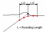
Rounding Length
specifies the length used to round the end condition. When this value is something other than 0.0, 4 additional points are added to the end of the end condition using a parabolic formula to smooth out the transition of the intersection of the end condition with the surface. This rounding effect is only applied when the target is a surface or an elevation. Any other end conditions attached to the end of this one is attached to the end of the rounded section.
Overlay/Stripping Properties
specifies properties visible for Overlay/Stripping components.
Top Option
specifies how the top of the component is defined.
Follow Component
specifies the top of the component will follow the defined top of the component.
Follow Surface
specifies the top of the component will follow the surface.
Follow Highest
specifies the top of the component will follow the highest of the component or surface.
Bottom Option
specifies how the bottom of the component is defined. The behavior of these options can be different, depending on the selected Top Option.
Follow Component
specifies the bottom of the component will follow the defined top of the component at the defined depth, but will not go above the top of the component.
Follow Surface
specifies the bottom of the component will follow the surface at the defined depth, but will not cross over the top of the component.
Follow Lowest
specifies the bottom of the component will follow the lowest of the component or surface at the defined depths.
Follow Highest
specifies the bottom of the component will follow the highest of the component or surface at the defined depths.
Component Depth
sets the depth of the bottom below to the defined component line. This value cannot be negative.
Surface
defines the surface to follow along. Does not support aliasing.
Surface Depth
sets the depth of the bottom below the surface. This value cannot be negative.
Alternate Bottom Surface
if this field is populated, when alternate surfaces are created from the Roadway Designer Create Surface command, the bottom of this component will generate an alternate surface of the specified name.
Label (Component Depth/Surface Depth)
parametric label, used to change the default depth(s) from within Roadway Designer.
Stripping Component
defines whether this component is designed to remove material or add material. Used in end-area volumes.
Apply
saves changes to the component.
Next
proceeds to the next component in the template (ordered left to right, top to bottom based on their upper left-most range point).
Previous
returns to the previous component in the template.